Just created new GitHub repositories for remote node code and put links to them on the page here on blog.
In the code there is visible declaration of sensors and authentication units, and their way of registration to gateway. In the iButton node, there is also sound and led code that is based on tone library and performs feedback to user. Wired nodes use my own RS485 library, otherwise standard Arduino libraries are used.
Monday, December 28, 2015
Wednesday, December 23, 2015
New node

There are many changes, while keeping the current format 5x5cm, I have replaced most of the components. There is new switching power supply, actually two of them. One is for standard DC 5 - 20 V and up to 500mA. Second is for batteries and support voltage from 2 to 5.5 V but only 120mA. There is still present the RS485 half-duplex IC, speaker, and header for 1-Wire touch probe with 2 LEDs. IO Header grew with new pins and most importantly there is place for new RFM69W radio module on the back.
I have plans to use more battery powered nodes that should last long. Either to run them from rechargeable batteries like li-on or li-po or from standard packs or bigger button batteries. Waiting for the boards to get them alive :).
Thursday, November 5, 2015
Redesigned UI
As always, I will push all updates to GitHub.
Tuesday, October 27, 2015
New design
It has been a while when I started real world testing of the whole system. I have polished the code, fixed
few bugs. Now I'm deciding that do next. I have few things on mind:
1. Design new PCB, bigger with all things on it. I have moved from Eagle to KiCad, and curently designing something like this:
 It has WizNet W5500 Ethernet chip, SIM900 for GSM, and also some other improvements like better analogue protection. Size would be 10x15cm and it will be drop in replacement for any old wired burglar alarm.
2. Move the software to Arduino 1.6 to resolve the last bug with SPI transactions. Ethernet library disables interrupts and very seldom some interrupts are missed, causing a radio or RS485 packet to be not seen. That would mean to rewrite libraries too, namely W5500 and RFM12B.
3. Port the RTOS from Nil to newer version called ChibiOS RT that allows dynamic threads and dynamic allocation of memory. This would eliminate the static allocation of memory for sensors and keys taking up RAM even if not needed.
For me all that work for many months is just fine, but I would like this to maybe become some kind of community project, so I'm not alone in this. I would gladly accept any hints, help in coding or design, or give some help to anyone.
Let me know...
1. Design new PCB, bigger with all things on it. I have moved from Eagle to KiCad, and curently designing something like this:

2. Move the software to Arduino 1.6 to resolve the last bug with SPI transactions. Ethernet library disables interrupts and very seldom some interrupts are missed, causing a radio or RS485 packet to be not seen. That would mean to rewrite libraries too, namely W5500 and RFM12B.
3. Port the RTOS from Nil to newer version called ChibiOS RT that allows dynamic threads and dynamic allocation of memory. This would eliminate the static allocation of memory for sensors and keys taking up RAM even if not needed.
For me all that work for many months is just fine, but I would like this to maybe become some kind of community project, so I'm not alone in this. I would gladly accept any hints, help in coding or design, or give some help to anyone.
Let me know...
Friday, August 14, 2015
Code update

Thursday, May 28, 2015
Remote unit demo
As you can see in the video I have the unit mounted
next to switches, directly in the wall. I found it very fast and easy
to arm/disarm the group. My 5 year old daughter still finds it funny
after 3 months of use and she ask for my keys to do it.
Thursday, May 14, 2015
GSM and uptime
some problems with his network. Luckily the thread that check GSM status handled the network failure just well, and recovered from it without issues.
 I have the system up and running for 96 days with all threads working. I
 must say the NilRTOS is really robust.I'm planning some software updates, but I have to create remote ISP first.
Also recently I have got W5500 chip and Wiz550IO and I'm very tempted to create a new mainboard together with SIM900. This would be all included alarm board that can simply replace old alarms and offer many features with open firmware and hardware.
Tuesday, April 7, 2015
Web interface - home

More important are the last three buttons. Starting from "Reset to default" that will wipe all configuration that is kept in the system RAM and replace it with "factory default". You would do it only in case you really want to start from beginning. The "factory default" must be confirmed by pressing any "Save all" button, so the changes are just loaded into RAM but not stored into EEPROM. You can go and take the last stored configuration in EEPROM by "Load last" button. "Load last" can also be used when you change temporarily any configuration in RAM for test cases. Just remember that in case of power loss the system stores current configuration form RAM to EEPROM just before the main backup battery is depleted.
Tuesday, March 3, 2015
Test run - stability

This brings me to an idea, does anyone want to have PCB for this project? Let me know, I have some spare ones, and will send them to you for 6-8 EUR (10$), depending on your location.
Wednesday, February 18, 2015
Web interface - log

Physically the log is located in 512kb I2C controlled EEPROM, and the logging mechanism using 16 bytes for every event. This makes together maximum number of 4096 log messages stored. Any call to log message function pushes the message to FIFO along with actual time stamp. Then there is a logger thread that takes care about the EEPROM circular buffer, and also about the SMS. Every message can be send as SMS to appropriate group of people.
The message itself looks like this:
150218104158;SCW
As you can deduce the "15 02 18" is date, "10 41 45" is time, next is the status of SMS function:
- "." requested, failed
- "," not requested, failed
- ";" not requested, acknowledged
- "|" not connected
- ":" sent
Logger thread also pushes all messages into following MQTT topics:
OHS/Log 150218104158;SCW
I'm planning to create on/off button for MQTT push.
Saturday, February 7, 2015
Web interface - sensors

- Temperature
- Humidity
- Pressure
OHS/Zahrada/Sensor/Temperature/0  23.00
OHS/Zahrada/Sensor/Humidity/0  53.00
OHS/Zahrada/Sensor/Temperature/1  24.04
OHS/Zahrada/Sensor/Pressure/0 998.38
OHS/Dilna/Sensor/Temperature/0   9.48
OHS/Domek/Sensor/Temperature/0  13.02
OHS/Garaz/Sensor/Temperature/0  12.06
Last setting is the group name the sensor belongs to.
Sensors are dynamically added when they first join the network. The Sensor type can be chosen to any possible, as long as its value can be stored i a float variable. Main unit does not care about the sensors at all, it doesn't do any computation with it values, and also it does not verify the content. Main purpose is to act as a gateway for MQTT to NodeRed or similar tool. Only value that indicate the health of the sensor is time-stamp called last OK, that indicates delivery time of last message from sensor.
Sensors are defined in the code by following struct:
  uint8_t address;
  char    type;
  uint8_t number;
//          |- MQTT publish
//          ||- Free
//          |||- Free
//          |||||||- Group number
//          |||||||- 0 .. 15
//          |||||||-
//          |||||||-
//          ||||||||-  Enabled
//          00000000
  uint8_t setting;
  float   value;
  systime_t last_OK = 0;
In the future, the parameters for sensors, and also for authentication units, will extend as they will be battery monitored. I would like main board to take care of the sensors battery life in form of some flag and also sms.
Monday, January 26, 2015
RS485 protocol
 Last post reminded me to write about library I have created for the wired network. It is called simply LibRS485, or NilRS485 adopted to work in NilRTOS. The library defines packet protocols on RS485 drivers. I use ST3485EB a 3.3 V powered, 15 kV ESD protected and up to 12 Mbps RS-485 half duplex transceiver. Inexpensive SO8 chip that has all that is needed already inside. As it is half duplex we need one extra pin to tell the transceiver if we are receiving or transmitting. The transmission itself require one twisted pair of wire and is able to push the data to distances over 1km with reasonable speed. The nice thing about RS485 it uses a differential balanced line and resists electromagnetic interference from motors and other equipment, more can be found on wiki.
LibRS485 uses a 9bit protocol and Multi-processor Communication mode defined in ATmega. This allows the MCU to do other thing without looking on communication unless there is a address frame. Basically i work like this:
- All nodes are in Multi-processor Communication mode (MPCM)
- One of the node sends an address frame, and all receive and read this frame.
- All nodes reads the address frame and determine if it has been selected. If so, it clears the MPCM, otherwise it waits for the next address frame and
keeps the MPCM setting. - The addressed node will receive all data frames until a new address frame is received.
- The other nodes which still have the MPCM bit set, will ignore the data frames.
- When the last data frame is received by the addressed node, the addressed MCU sets the MPCM and waits for a new address frame. The process then
repeats from 2.
 -------------~~~~~~~~~~~~~~~~~~~~~~
 - A - P - X -  D0 - D63 ~ S0 ~ S1 ~
 -------------~~~~~~~~~~~~~~~~~~~~~~

  - Required fields
  ~ Data and signature fields
  A Address - 4 bits form and 4 bits to address.
    0  is master, but not really as any node can drive communication
    15 is broadcast to all
    14 addresses left for other devices

  P Packet definition - 2 bits type and 6 bits length.
    Flag bit configuration:
    FLAG_ACK 3
    FLAG_NAK 2
    FLAG_CMD 1
    FLAG_DTA 0

    Types: CMD - Command - user defined general commands value 0 - 63
           DTA - Data - user data length D0 - D63 and CRC S0, S1
           ACK, NAK - flags for data, using signature of data packet

  X XOR of A and P, for basic transfer safety.

  D0 - D63 user data.

  S0 ~ S0  CRC for user data or signature for ACK, NAK.
So basically there are two types of packets. Command packet that has only 3 bytes (APX) and deliver a command(number 0-63) to node(s). It is used for example to issue a call for registration. Or data packet that has 6-69 bytes (APX D0~D63 S0S1). This deliver any data to node(s). The nodes are addressed by its address 0-14, which select any individual node. Or address 15 that is broadcast to all nodes.
Friday, January 16, 2015
Web interface - authentication
 Authentication units have their own configuration page as shown on the right. On the top, again, is a summary of authentication units connected to system. The units can be connected by wire(RS485) or wireless(RFM12B). It is shown in the address field. "W" stands for wired and "R" for Radio. Address range is the decision maker here. Units in range 1-14 are wired and 17-143 are connected wireless. Address and type of the authentication unit is defined in remote unit itself. The few options to set is turn the unit On or Off, other is to attach them to certain group.
Remote units are dynamically added to the system at any time by process called registration. This process is activated by service thread few seconds after the system starts, or when you power up any remote units it will issue call for registration. If the unit is present already the system will re-reregister it with new parameters. The actions taken are presented in the log. You can for example see following messages:

If you miss any unit that should be there you can push "Reregister" button and the system will issue registration call.
Going little more in detail, the all the settings are permanently stored in remote units in-chip EEPROM. By default the units register with their defaults, that is not enabled and belonging to group 16. And you have to set them on first. The other settings like functions they provide is dependent on the hardware and is coded in the registration message they sent to main board. Any remote unit can provide more then one function, as you can see on picture above. Unit 1 is iButton authentication unit and also provide ambient temperature.
Monday, January 12, 2015
Web interface - phone numbers
 Web interface also include phone numbers setup. There is now space for 8 numbers. On the top you can see the overview in a table. Bellow there is selection button to chose to work with entries. Phone can be enabled or disabled, so you can temporary take anyone out. You can create unique name for every phone number for convenience. And it will appear by this name on other configuration pages. If you set "Global" option to yes the number will be informed about any event. As opposed to "Global No" the number will be informed only about group specified events. This page only specifies the setting for individual numbers, selecting which event will be passed is done in global configuration page.
Friday, January 9, 2015
Web interface - keys
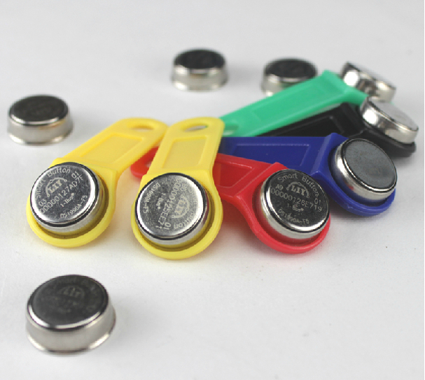
 Another configuration page is about iButton keys. You can see the page on the right. Settings here are rather simple on the top you can see the table of assigned keys. There are name and and 8 byte address of iButton key. There is currently space to store up to 8 keys, but can be expanded. Bellow that is a pull down selection to work with single key. There is not much to say about that except of last key value that is set to 55's. This value hold the last unauthorized key address. That can be used either to see address of key that is not yours. Or better when you have new key, you can just touch authorization unit. The system recognize unknown key, issue a warning message in the system log, and store the address value here. Next thing is to copy paste the value to some empty slot and give it a name, and press "Save all" to update the EEPROM. Well there is also laser printed address on every iButton, but in reverse order and it is bit tiny.
The system uses just ROM address of iButton, that mean you can use any iButton as a key even temperature probes and such. Now this bring another thought about security. First I consider iButton secure, but they can be read and copied, so can be RFID tags. Also touching probe with iButton is more convenient than to type 16 hex digit on keypad. But it can be surely improved. For example if you stay with iButton there is NVRAM version like DS1992. It gives you 1Kb of non volatile RAM you can use for floating code that can be generated every time you touch authorization unit. This makes coping much more complicated.
Subscribe to:
Posts (Atom)