Groups

zones, authentication units, sensors and contacts. It allows you, for example, to set different alarm settings for your house and for your garage. Your garage can be armed and monitored while you are present in your house. Groups have it's own tab on web interface, and you can see there what zones, authentication units and sensors belong to which group, and what contacts are informed about group events.
The group itself does not have too much settings. You can set the group name, set it On or Off and assign a output of gateway relay trigger for PIR and tamper events. Since version 1.7.6.0 it is also possible to set auto arm for group. Auto arm scan all zones in a group for newest alarm. That is, if there is someone moving in at least one zone in a group for given period, the group will not become auto armed. Last setting is group chained arming or disarming. That is while arming/disarming one group manually with key, you can configure gateway to select another group to do the same. It can be useful, as shown on picture, to arm automatically Garage when you arm House group. This is set separately for arm and disarm, and groups can be chained. Even the chain can be made as circle, that is House -> Grage -> Barn -> House, this way anytime you arm one of these three groups all will become armed. When you do not need any chained group you leave it set to the same group.
All other parameter are taken form their respective sources like zones, sensors and such. But group setting offers great overview of what is going on in your system. You can see the group status, if it is armed or alarm is tripped and so on.
There are 16 groups not only to differentiate zones, but also to distinguish location of sensors and to allow proper MQTT propagation. When there is new element(zones, authentication units, sensors and contacts) it is automatically added as disabled to group 16.
Knowing this create your groups by enabling them, then name them and
assign them relay(siren) outputs. There are two relay outputs for 2 sirens, usually one outdoor and on indoor. OUT setting allows you to make combination for different alarm and tamper events or groups.
Global setting

Right after you create few groups, you should set and understand four global settings that have impact on them.These settings on right picture are present in Global tab. Authentication time is base time for delay, that gives you time to authenticate and disarm group. It is further expanded by zone authentication time multiplier, and covered later in Zones setting.
Arm delay is time period between arm signal and group arm state, it gives you time to leave the armed group before it's armed.
Auto arm delay is time base for group to become auto-armed if there is no activity in all zones of such group. Auto arm can be enabled by group, and it is meant somehow as safety feature in case you are frequently forgetting to arm such group.
Open alarm is time base for another feature reminds you that zone is in alarm state for longer then specific time. This can be used if you have reed switch sensor on your back door or garage. Open alarm has to be enabled in specific zone as well, then gateway will notify you by SMS, email or page you.
Authentication units
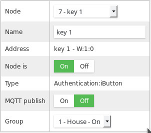 Having groups set, it is time to assign them authentication units(nodes). You will find them in Nodes tab. Every group needs to have at least one authentication unit to disarm and arm it. I wrote disarm first as group can become armed by itself , or tampered. When zone is tampered it forces its superior group to alarm state and you will need to disarm it.
Settings are present on picture. Basically you have to enable it, then give it some friendly name and assign it to right group.
Zones

There are two different type of zone, local zone and remote zone. Local zones are directly
connected to gateway hardware. These can be build in 8 analog plus 4
digital zones, or zones connected by I2C expansion connector. Then
remote zones connected either by RS485(wire) or wireless zones.
Connection type does not matter to gateway, but such zones can be
divided to two groups by reporting state. One group would report fully
its state, that is it will report every change of state out of OK, PIR
or Tamper. The other, battery powered remote zones, will only report
alarm states such as PIR or Tamper. Gateway will then automatically
change the zone state to OK if there is no event received for 2 seconds.
Zone settings are shown on picture. You can give a zone a friendly name and set it On or Off at any time.
Open alarm is enabling the zone to be monitored for long alarm state. Such feature reminds you that zone is in alarm state for longer then
specific time. This can be used if you have reed switch sensor on your
back door or garage and you keep it open.
Alarm as tamper forces the zone alarm state to tamper state, it is useful for digital zones, and is set by default for the enclosure tamper contact (zone 13).
Authentication delay is zone setting for authentication time multiplier for given zone. Put it simple is time that gateway waits when current zone is tripped. For entry door sensor you will set it to 1~3, based how much time you need to reach the authentication unit. For you window zone, or inner house PIR sensor you will set it to 0, no need to wait for authentication when someone enters your house through window.
Group assign zone to specific group.
Triggers

Triggers is new option in firmware 1.7.3, it offers automation of events on sensors or zones. There can be up to 10 triggers created that can do various task or react on zone state or sensor value.
The setting of each trigger is shown on right. You can assign name up to 15 characters for each trigger and turn it On or Off. Important is the source address, that is the sensor or zone number, that triggers the subsequent action. Symbol is condition describing when the trigger should happen. Put it simple, it is "if ... then" in code. There can be "=","!","<",">","A", that is equal, not equal, less then, more then or always. Value is a float number that the condition is compared to, except for symbol always that is processed anyway. Hysteresis is value to smooth constantly changing values to relay output. Let's say you want to turn fan on when humidity is 55%, and you'll set Hysteresis to 5%. The actual on will be then send at 55+5 and to Off signal at 55-5. Then there is logging flag, it means the trigger event is passed to logger, which can then send SMS or email, based on logger setting. Pass flag will indicate that when the event is triggered, gateway will pass the value to To address sensor. Pass once flag is preventing subsequent sending of value for same trigger, and it is reset when condition is negative. Pass Off will send first off message to recipient after the condition is negative. Pass value or constant switch is deciding if a source address value is passed to destination address or the constant present in Constant On and Constant Off.
With triggers you can dynamically assign many events that can help you improve your home automation directly in friendly web interface. For example there can be trigger to send SMS or email when battery is reaching low level on my meteo station. And second will turn on light whenever there is PIR sensor triggered on zone called stairs. Simple as that, and it just works!
You can create many other scenarios for triggers, such as simply passing data from one sensor to another. I have in mind passing external temperature and humidity to internal temperature and humidity sensor that turns On/Off fan in bathroom. This way you can compare the two values and make better decision.
Timers

There are 10 separate timers present in firmware. The overview is present in table, and as always all setting of timers is available over the GW web interface. Timers are divided to two different kinds. One called Period and other Calendar. The main difference between them is how they handle days of week. Calendar based timer can run only once a day at any given start time you provide. And you can select what day or days of week it will run. Period timer will run repetitively at every period time starting at given start time. Period time can range from 1-255 seconds, minutes, hours or days.
Both of types of timers have in common run time setting which specify the time between On and Off signal to remote node. It again ranges from 1-255 seconds, minutes, hours or days.
All setting for timers are shown on right picture. Every timer can be identified by name, and can be turned On or Off at any time. There must be taken some caution when turning Off timer that is triggered, it would disable the Off signal sent to remote node and it will be left On. Then there is the mentioned Period and Calendar switch, and later on seven switches for every day of Calendar timer. These day switches have no functionality for Period timers. Start time on the other hand has meaning for both, Calendar timer will trigger exactly on this given time at any selected day. Period timer uses the Start time as offset of its first calculated period interval. Period time and Period interval together make the desired scheduled start for Period based timer. And Run time and Run interval make the desired scheduled end for both types of timers. To address selection lets you assign any node in your wired or wireless network that is capable of input function. Then Constant On and Off are the values that are sent to such node at start and stop time.
Hi Great project. I gone through the web configuration of the gateway. I believe you missed something for RS485 modbus configuration. Especially, for single slave or multi slave an its parameter.
ReplyDeleteHello,
ReplyDeleteI do not use modbus, I use only RS485 as transfer medium.