I created this board to use it as base for various battery powered sensors I use at, and around my house. It is evolution of my Radio Mini Node based on ATmega328P, but instead of ATmega, it's using STM32F103 (basically well known BluePill). It suited for RFM69HCW(CW) or various LoRa RFM9X(RFM95/96) modules. It can have an u.UL connector for pigtail, or it has a solder pin for simple wire antenna. It comes with micro USB charging for 3.7V Li-ion cells with capacity ranging from 500mAh to 2000mAh. Quite good are 102050 (1000mAh) or 102550 (1500mAh) with JST-PH2.0 connector, that are almost matching the size of this board. It also includes battery voltage measurement connected to MCU analog pin. USB port can be used for programming, or as serial port. It has also standard ST-LINK SWD port. There are RESET and BOOT0 push buttons for convenience. Then there is also external RTC quartz crystal which allows indefinite sleeps instead of ATmegas maximum 8 seconds. It has LED on PC13. Also on top, there's a place to mount various temperature/humidity sensors like HTU21D. PCB comes with mounting holes to fit in various places.
Specification is as follows, it's STM32Duino BluePill compatible board with STM32F103C8:
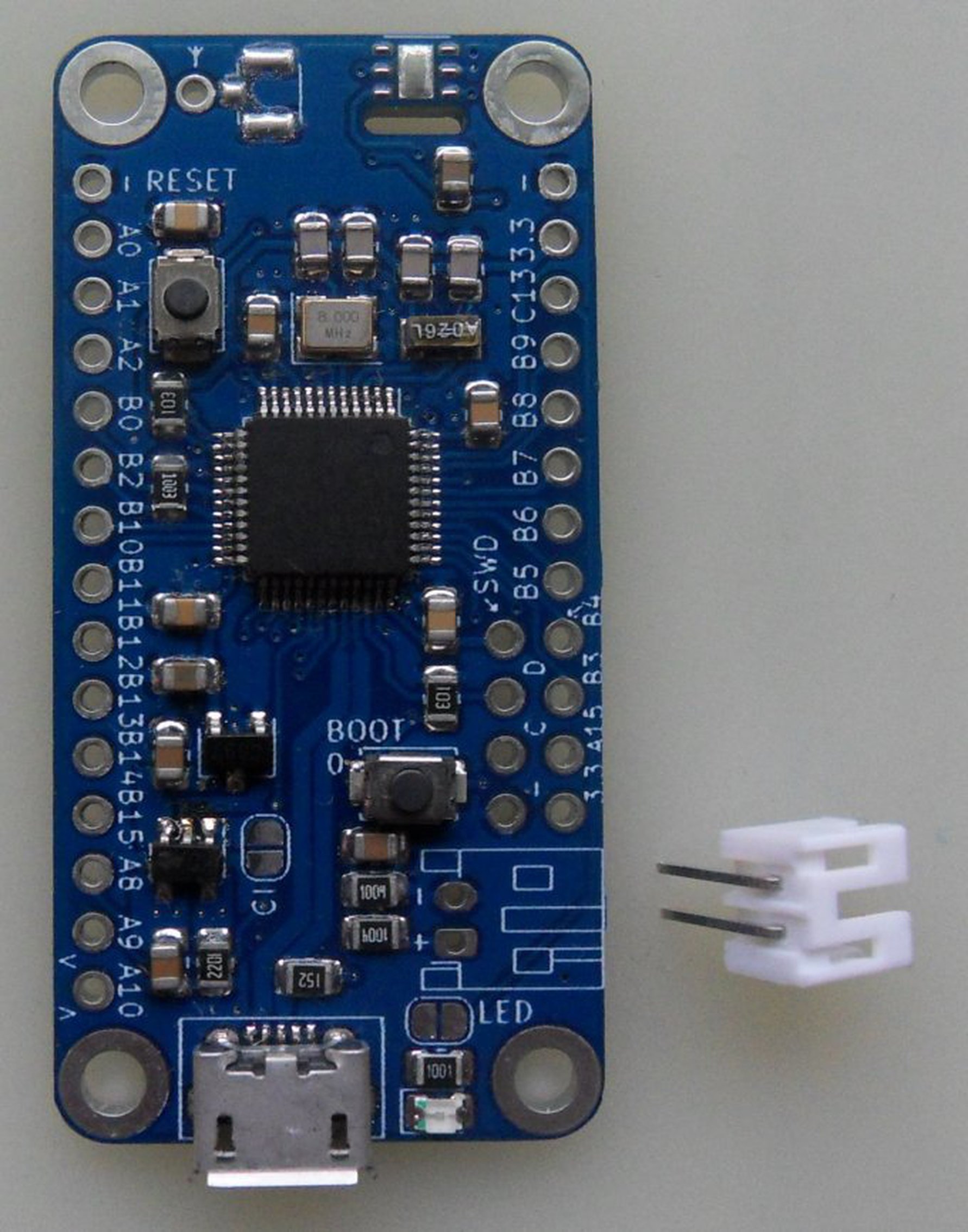
- Size 24 x 49 mm (0.95 x 1.92 in)
- STM32F103C8 - FLASH 64KB, SRAM 20KB, Max. 72MHz @ 3V3.
- 8MHz main crystal, RTC 32.678kHz crystal.
- USB charging designed for 3.7 Li-Ion battery (500 - 2000mAh). Great thermal dissipation.
- Included, but not soldered, JST PH2.0 battery connector.
- Charging state (Hi-Z) available on pin PA8 via NO(Normally Open) PCB jumper.
- Voltage measurement on PB1 pin via 2:1 voltage divider, consuming 2,1uA @ 4.2V.
- LED on PC13, with NC(Normally Closed) PCB jumper.
- ST-LINK SWD 4-pin connector (3V3, SWDIO, SWCLK, GND).
- RESET and BOOT 0 push buttons. BOOT 1 (PB2) pulled-up by 100k resistor.
- SPI1 routed to RFM69/RFM9X modules. PA4(CS), PA5(SCK), PA6(MISO), PA7(MOSI)
- NO PCB jumper for Radio Reset routed to PB11.
- NC PCB jumper for Radio Interrupt(DIO0) routed to PA3
- PCB footprint for HTU2XD, SHT2X, SI70XX humidity/temperature sensor routed to I2C.
- Optional HTU21D humidity and temperature sensor.
- RFM69HCW 868Mhz as soldered on option.
- Optional u.FL antenna connector.
- Optional high quality 20cm u.FL to SMA pigtail.
- Optional rubber SMA 868/915MHz antenna.
The consumption of the board alone is around 60uA while MCU is in deep sleep, when clocked at default 72MHz. With soldered on RFM69HCW radio module and temperature/humidity HTU21D, the consumption raises to around 120uA while sleeping. This is about the same as a normal Li-Ion 1500mAh self-discharge current. It is enough to keep the node sending packet every 10 minutes for many months with a 1000mAh battery.