
Power connector.
Gateway needs 12V power supply, check my store if you need one. As shown on picture from left the terminals are:
- GND.
- 12V, allowed range is 11 - 14V. There is no polarity protection, but the input is fused and over voltage protected.
- Battery OK, signal input pulled up by resistor to 3.3V. If signal is low gateway assume that battery is under 11V.
- AC Off, signal input pulled up by resistor to 3.3V. If signal is high gateway assume that AC power was turned Off.
Standard Cat5 and higher cable, uses 10/100 Mbps half/full duplex with auto negotiation.
Antenna connectors
On PCB are only IPX U.FL coaxial connectors for both GSM and RFM69. You will need a pigtail and antenna. I sell them optionally in my store. It is recommended to use hot glue to keep the IPX connectors from pigtails on PCB. It can happen that you by accident unplug it and it may short some exposed pins of 4V or 12V rails.
Connecting balanced sensors, PIR, smoke, MW
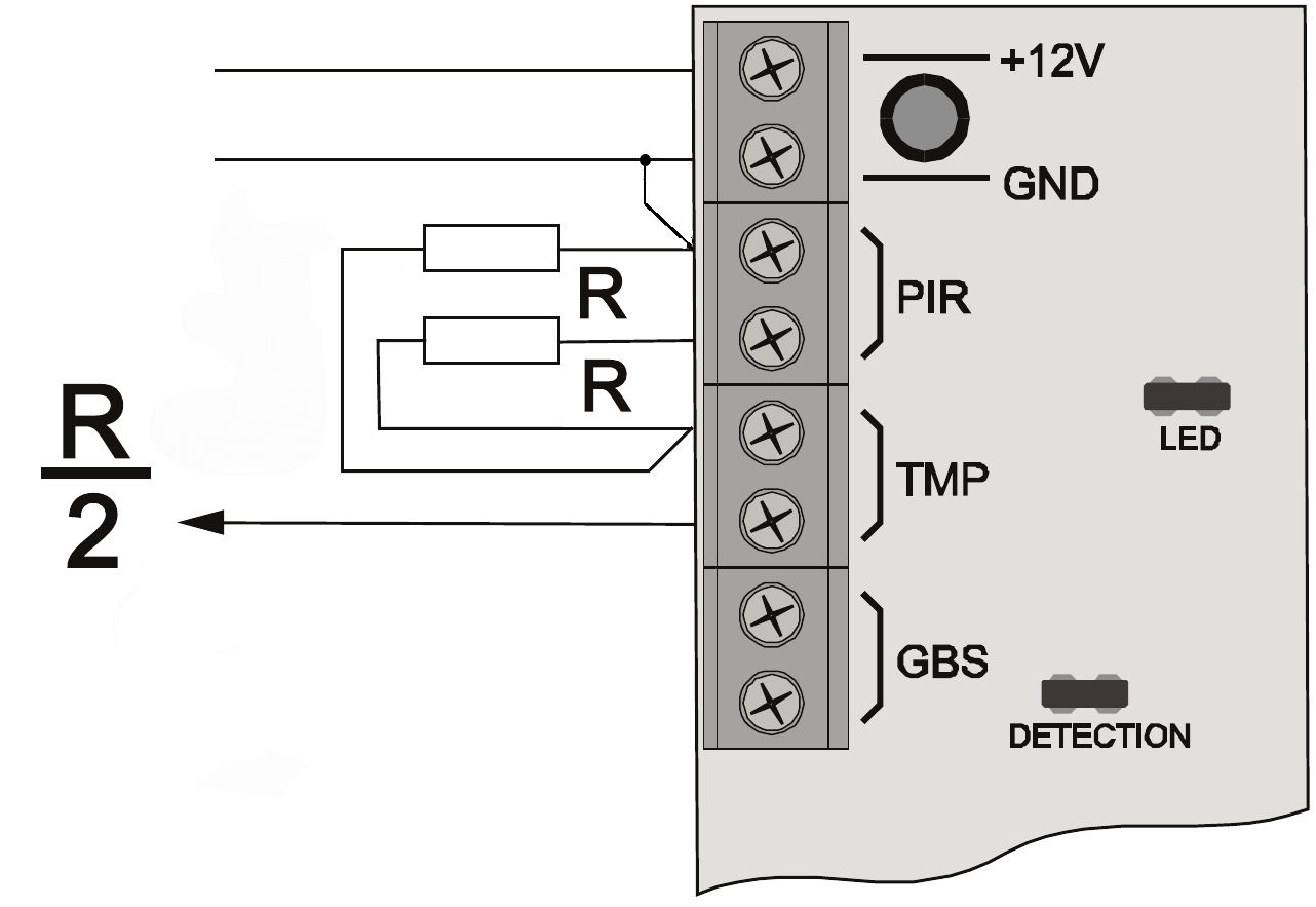 Picture on right side shows how to connect balanced PIR sensor, there are only 3 wires needed to connect a PIR to gateway. Best would be use of 3 or 4 wire AWG~22(0.3mm2) cable, but this would be normally expensive. I use for wiring CAT 5e/6 cable a use half of the wires, or I connect 2 nearby PIR sensors to one CAT 5e/6 cable. Good practise is to use 2 wires for ground.
Wiring is following:
- +12V wire goes to 12V terminal on PCB. 12V on gateway is fused by 200mA self recovery fuse.
- GND to GND. remember the ground of balanced sensors is separated from rest of GND, and should not be interchanged with other GND terminals.
- Arrow from picture is the signal that is connected to PCB terminal A1-A8. Inputs are over voltage and surge protected.
There is possibility to daisy chain the sensors in one loop, but then you need 4 wires and the resistor divider will be present only on last sensor in chain.
RS485 and terminator
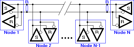 RS 485 network require one twisted pair cable. On each end it requires a
 120Ohm resistor. For convenience gateway and all wired nodes have selectable terminator by jumper on PCB. Wired nodes are also prepared to receive power from gateway. Similarly to balanced PIR sensor, 4 wires of standard Cat5 cable can be used to transmit both data and power. Connect A to A, B to B, GND to GND, 12V to 12V. Position of gateway in network does not matter, it can be one one end or it can sit in the middle. A 100m long bus is no problem for RS485 network. Gateway software can address 14 nodes.
Unbalanced sensors and tamper.
Unbalanced sensors have only 2 possible states, and they are good for door or window reed switches. Usually you can connect the reed switch to door with use of rest of wires from Cat5 wired RS485 authentication nodes. Gateway assumes closed circuit as OK, open as alarm. For reed switch you will need only 2 wires, connect 12V to one contact of reed switch and D1 - D4 to second contact. There are also GND terminals for convenience, in case you will need to power smoke or other more complex sensor.
Tamper terminal contacts are present to set alarm On in case you wish to monitor unauthorized access to gateway enclosure. Similarly to sensors, gateway assumes closed tamper contacts as OK.
Relays and relay source switches
Gateway has 2 software selectable relays, that are able to switch On horn or siren. The relay switch jumpers make selection if common contact is feed from 12V internal source, that is it provide power to siren. Or if the common contact take input from terminal contact. Relay has both NO and NC taken out to terminal.
Gateway programming
Standard 3V3 FTDI serial port is present for firmware update. Gateway have Arduino bootloader.
Gateway 1.x first start
When you flash new firmware or start gateway for first time, it will receive IP address from DHCP. You should find the address based on your local network setting, there are software for it. For Windows(http://angryip.org) or in Linux(nmap). You would be looking in default MAC: DE AD BE EF FE ED, or what ever MAC address you set during compile time. Another option is to attach serial 3V3 programmer to connector labelled FTDI and open terminal connection(115200 bps, since 1.7.6.5 38400). You should see the DHCP addresses obtained on screen like:
DHCP: 1
IP: 10.10.10.122
GW: 10.10.10.254
Mask: 255.255.255.0
Open the web browser and enter the found IP address. Then follow the steps:
- The gateway should prompt you for user and password, default is # and #. While in web configuration interface open Global tab, and change the system user and system password to whatever is desired. Maximum length is set to 10 characters. Press Apply, page will reload. Enter the newly created credentials.
- Go to Home tab and set a key for radio module. Key needs to be exactly 16 characters long.
- Choose which frequency you prefer for RFM69, that is 868 or 915 MHz.
- While in Home tab, set your daylight saving start and daylight saving end setting depending on your actual time zone in respect to UTC.
- Next, set you nearest NTP server IP address, default is server located in Czech Republic - Europe. And you would need something near you. For this you would look around Google and use some "stratum 2" or bigger server. Then press Get NTP time and you should see updated time and date as well as daylight start and stop times.
- Open Network tab and set gateway IP address. Network Gateway address(your router IP address), and network mask. You will see there DHCP values, and you would only need to change the gateway IP address, if you are not happy with default DHCP.
- On same tab change your MQTT sever IP address and MQTT port. MQTT server IP address is used to verify the connection to network. That means GW will try to reset its own Ethernet driver if it does not find running MQTT server, and you will experience connection drops in web interface.
- Press Save all, this will save your setting to internal EEPROM.
- Reset the gateway by reset switch on PCB. Better is to hold it for more then 0.5 seconds then quick press as all the peripherals need to reset itself as well.
- You are done!
No comments:
Post a Comment