Showing posts with label RFM69. Show all posts

Friday, October 27, 2023

Updated Radio NodeMini with STM32

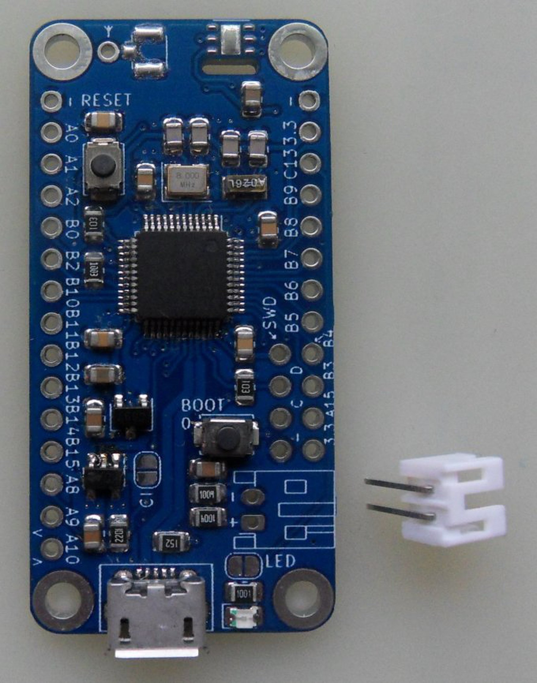
Here comes the updated version of Radio Node Mini on STM32f103. There are only a few visual changes, like places for the required pull-up resistors for the I2C bus. I add them automatically when someone orders the optional HTU21D temperature/humidity sensor. Other than that, only silkscreen labels are enhanced. But the most important fact is the change of way I make those boards. 

The chip crisis is fading out and with it all the components are getting cheaper. This brought me to an idea to use fabrication services. And since I'm getting busier and I value my free time even more, I tried to compromise and I let the new nodes be assembled and soldered at the PCB shop. I invested the effort into making a small panel of the boards and created BOM and CPL files for the machine assembly. 

Make it short, the service is great. Actually it allows me to lower the price of the Mini Nodes, simply because it takes me much less time. And not only by saving my labor time, but also the components are priced similarly, or sometimes even cheaper, to my preferred shop TME. There are only a few cosmetic problems with the micro USB ports, or the micro buttons which are not always aligned, but the boards are nicely soldered and even cleaned of the residue flux.

To celebrate this accomplishment, I made a new graphical pin-out diagram for the STM32 Radio Nodes Mini. Take a look:


Friday, January 6, 2023

STM32 Radio Nodes Mini

STM32 Radio Nodes Mini are here and available for sale in my shop and on Tindie.com

I created this board to use it as base for various battery powered sensors I use at, and around my house. It is evolution of my Radio Mini Node based on ATmega328P, but instead of ATmega, it's using STM32F103 (basically well known BluePill). It suited for RFM69HCW(CW) or various LoRa RFM9X(RFM95/96) modules. It can have an u.UL connector for pigtail, or it has a solder pin for simple wire antenna. It comes with micro USB charging for 3.7V Li-ion cells with capacity ranging from 500mAh to 2000mAh. Quite good are 102050 (1000mAh) or 102550 (1500mAh) with JST-PH2.0 connector, that are almost matching the size of this board. It also includes battery voltage measurement connected to MCU analog pin. USB port can be used for programming, or as serial port. It has also standard ST-LINK SWD port. There are RESET and BOOT0 push buttons for convenience. Then there is also external RTC quartz crystal which allows indefinite sleeps instead of ATmegas maximum 8 seconds. It has LED on PC13. Also on top, there's a place to mount various temperature/humidity sensors like HTU21D. PCB comes with mounting holes to fit in various places.

Specification is as follows, it's STM32Duino BluePill compatible board with STM32F103C8:

  • Size 24 x 49 mm (0.95 x 1.92 in)
  • STM32F103C8 - FLASH 64KB, SRAM 20KB, Max. 72MHz @ 3V3.
  • 8MHz main crystal, RTC 32.678kHz crystal.
  • USB charging designed for 3.7 Li-Ion battery (500 - 2000mAh). Great thermal dissipation.
  • Included, but not soldered, JST PH2.0 battery connector.
  • Charging state (Hi-Z) available on pin PA8 via NO(Normally Open) PCB jumper.
  • Voltage measurement on PB1 pin via 2:1 voltage divider, consuming 2,1uA @ 4.2V.
  • LED on PC13, with NC(Normally Closed) PCB jumper.
  • ST-LINK SWD 4-pin connector (3V3, SWDIO, SWCLK, GND).
  • RESET and BOOT 0 push buttons. BOOT 1 (PB2) pulled-up by 100k resistor.
  • SPI1 routed to RFM69/RFM9X modules. PA4(CS), PA5(SCK), PA6(MISO), PA7(MOSI)
  • NO PCB jumper for Radio Reset routed to PB11.
  • NC PCB jumper for Radio Interrupt(DIO0) routed to PA3
  • PCB footprint for HTU2XD, SHT2X, SI70XX humidity/temperature sensor routed to I2C.
  • Optional HTU21D humidity and temperature sensor.
  • RFM69HCW 868Mhz as soldered on option.
  • Optional u.FL antenna connector.
  • Optional high quality 20cm u.FL to SMA pigtail.
  • Optional rubber SMA 868/915MHz antenna.

The consumption of the board alone is around 60uA while MCU is in deep sleep, when clocked at default 72MHz. With soldered on RFM69HCW radio module and temperature/humidity HTU21D, the consumption raises to around 120uA while sleeping. This is about the same as a normal Li-Ion 1500mAh self-discharge current. It is enough to keep the node sending packet every 10 minutes for many months with a 1000mAh battery.


Saturday, December 8, 2018

Authentication unit over radio

Recently new user of OHS gateway has explored a slightly new way how use authentication units. That is normally until now, the authentication units are desired to be online when main unit is online. This was easily achieved when they were wired nodes with RS485 wired connection. The power and data were going to node over 4 wires, like in any industrial RS485 application. Same 4, or more, wires are usually installed in your house for old authentication units. And it is easy to use them switching old unit to new one.

But what to do in case you have no wires in walls and you want try it without too much construction work. Well, then use the radio as for sensors, right!.

For this reason there is new code example on GitHub. The code is build on RFM69 example, but adds parts of wired node where iButton, LEDs and speaker is used to complete a basic authentication node. I have tested it and it woks quite well without any issue. There were some changes needed in the gateway code, and I will soon post them to GitHub as version 1.7.6.3, along with other tweaks.

Of course there are some drawback over wired connection. It is recommended to have some battery backup for the node as well. That is use the USB node with charging and place a decent 1000mAh, or better bigger, battery. Still it can happen that the gateway is powered from it main 12V supply, and the authentication node battery is depleted and dies. In this case, when you arrive at home at this exact moment, you will not be able to disarm standard way, and you will face system alarm. It is probably not a security concern, but you'll annoy your neighbors a bit until you run to your gateway and turn it off. Thankfully there are two possible solutions. There is possibility to disarm over web interface, but unless you have battery backuped home network, you probably will not be able to do so. But, you can always disarm group over SMS command, this should work as GSM module is in the gateway.

Second problem can be radio connection. As for any sensor, the radio authentication can be out of reach of the gateway. While it is unlikely in normal house, you have to think about having at least RSSI of -75, so you are guaranteed to have room to some unexpected radio noise. It can be easily checked in web interface debug tab, incoming RSSI is reported on any received node packet.

Also, one have to keep the unit powered all the time from at least 500mA USB charger, some older cellular charger perhaps. As the node is not entering any sleep state, nor suspending the radio module, and consuming 20-40mA of power. It cannot be asleep, as it needs listen to receive all radio updates. Rest of power to 500mA is to charge the battery after power failure.

Still I think these small disadvantages can be accepted as trade off for fast deployment.


Tuesday, July 3, 2018

Radio node mini

There is now new basic sketch on GitHub that can be used as basis for integration of mini node to OHS. It registers 3 sensors, that is: battery voltage, TX power level and charging state. Sketch can be uploaded using Arduino IDE and selecting Arduino Pro Mini board, be careful to select proper crystal speed(16 or 8MHz) when uploading the sketch. Voltage selection in menu of Arduino IDE can be ignored as board works always with 3V3.

Just now I realized the board size is pretty close to standard SD card.

Also I will be mostly using simple wire antenna with this small boards. Here are length of wire that can be soldered directly to RFM69 pad:

433 1/4 wave = 164.7mm
433 1/2 wave = 329.4mm
433 full wave = 692.7mm

868 1/4 wave = 82.2mm
868 1/2 wave = 164.3mm
868 full wave = 345.5mm

915 1/4 wave = 77.9mm
915 1/2 wave = 155.9mm
915 full wave = 327.8mm

I personally use 868 modules and 1/4 wave length antennas.

Sunday, March 25, 2018

New wireless mini node

Lately I have stared to play even more with various remote sensors wirelessly
connected to OHS gateway. I have used my standard radio nodes, but its versatility is somehow to much for small wireless node. To save space and gain easier access to pins of MCU I have designed new node called Radio Node Mini. It resembles Arduino Pro Mini with ATmega328P, but it has place to mount RFM69 board on it. It also has micro USB connector for charging designed for 3.7 Li-Po or Li-On battery.

It is breadboard friendly and measures only 24.4 x 32.8mm (0.96 x 1.29 in). All available pins are taken out to board sides and marked as on Arduino board. It is 3V3 board and it is available with 16Mhz or 8Mhz quartz oscillator. As it is made to work with Li-Po or Li-On battery it features battery voltage measurement on A6 via 2:1 voltage divider, and also ability to detect charging state connected to pin D8. Pin D2 is not taken out as it will be used as interrupt pin for RFM69. It has also possibility to assign pin D4 as reset for the RFM69 via solder jumper labeled RR. Board is programmable via FTDI programmer. Note, that it is not able to take power from micro USB without battery, the charger is providing only minimal current to the board when it does not detect the battery. However FTDI programmer can be used also as power source while developing.

Board has excellent standby battery consumption within few uA when MCU and radio is asleep. It will last for months to year(s) depending on battery size and sleep conditions. Board is able to handle 500-2000mA battery. I especially like those flat 700-800mAh small quadrocopter batteries found on eBay. they are cheap, has similar size as the board, and have also protection circuit built in. Only drawback is that they have usually 100-150mAh less capacity then advertised.

Boards are also now available in my store for 7EUR fully assembled. As option you can choose radio module, pigtail and antenna.


Friday, May 26, 2017

Nodes


New nodes now come with blue PCB and as option with USB charger. Here on picture you can see battery powered node with USB charging circuit and temperature sensor. On back there is RFM69HW module, also available as option, and 720mAh Li-on battery. Such batteries can be found on ebay. They are sold for quadrocopter toys, and even they are labeled as 25C RC, they have build in protection circuit.


Further more I will, or I can, equip all battery powered nodes with 8MHz crystal oscillator instead of 16MHz. This reduce the power consumption even more. The whole setup on picture has following consumption:

ATmega328P@8MHz sleeping 33.2~33.6uA
ATmega328P@8MHz running ~4mA

Just to ones that are curious what are the missing components. This board can be either battery or DC powered, and also can communicate over radio(RFM69HW) or RS485.

Wednesday, February 8, 2017

Loose antenna connector

Doing some experiment on my testing gateway I have put new pigtail on. I like to leave the SMA connector little loose, as it sits on table and is able to lay down completely when I move it. Staring gateway up, I was not able get response from nodes located further away. And I started to check if automated power level feature implemented in RFM69 library is working properly. ... It ended up that I have added new sensor type in gateway as well as the example sketches for radio nodes called TX Power. It shows the current TX power setting out if possible 32 levels present in RFM69 chips, and translate them into 3-100% float value transmitted to gateway. I did not put 0-100% as 0% made me little worried :) Bellow is picture presenting data from my testing meteo node, now with TX Power level.


Just to say, all was working OK before I added this, only my SMA connector inner ring was too lose. It took 2 second work with piers to fix it. At least it brings nice new feature :)

Thursday, April 21, 2016

PCB for new GW board.

Little later that I wanted here is 3D picture of new GW PCB version 1.6. I have already send it for fabrication. Wish me luck. :)

There is still 1284P, new WIZ5500, SIM900, new dual power supply, new analogue protection circuit and RFM69HW. It comes in 10*13cm size and will have nice big connectors.

Friday, February 12, 2016

Battery node


New node boards have arrived. I've ordered first time from seeed, and they look quite good. Nice sharp traces, I use usually bigger ones, as I tend to hand solder sometimes. Nicely aligned solder mask, and silkscreen without smudges. I will use them in future for sure.
This board was also for me first board to be made in KiCad, instead of Eagle, as I needed bigger PCB area for new gateway(main board). I can just say all as expected, if you check your Gerbers, there should not be any surprise. I feel a bit more confident to spend $50 for the big boards.

So, speaking of hardware, I soldered the battery option node. There is place on PCB for either battery or DC or even both if you want dual power (3.3V and 5V). And it works! Happy man :). To put it in numbers:

Battery voltage is more then 3.4V:
ATMega328P, and HW69W both sleeping:  0.09mA
ATMega328P working , and HW69W sleeping:  7.2mA
ATMega328P working , and HW69W receiving: 8.5mA 
ATMega328P working , and HW69W sending: 61mA

Battery voltage is less then 3.4V:
ATMega328P, and HW69W both sleeping:  0.12mA
ATMega328P working , and HW69W sleeping:  14mA
ATMega328P working , and HW69W receiving: 17mA 
ATMega328P working , and HW69W sending: 123mA

I tend to use it with li-po batteries, in theory they have self discharge ranges about 5% in month, then 1–2% per month (plus 3% for safety circuit). By raff numbers, and using the scenario of a remote sensor sleeping for 5-10 minutes, reading the sensor and doing the math for 500ms. Finally transmitting for at full power for 10ms, it gives me battery life for about 2 years with 2000mAh battery.

Now the question here is where it is a practical and economical solution to buy a li-po and let it basically drain by self discharge. Eneloops NiMH have seems to be more suitable, but li-po's are getting cheaper on eBay or such. Another solution is to go for a small li-po, around 200mAh and tiny solar panel. This or another, I'm happy with its wide input voltage and consumption. With this setup I can go from AA, to li-po or NiMH.

Going back to design, it uses MCP1252, which is inductorless, buck/boost, DC/DC converter with low quiescent power: 80 μA (Typical), and giving 120 mA (150mA max, high power RFM69HW can be used) output current. Add couple of ceramic capacitors, and you are set. On picture capacitors a a bit bigger then pads, since I have put what I found in drawer, and not the proper 1206.